Subcontract CNC Lathe Part Inspection Criteria
Explore vital part inspection criteria in contract CNC machining, from GD&T and surface roughness to CMM checks and first article approval.
In the serial manufacturing of precision mechanical assemblies and security locking mechanisms, micron-level tolerances govern whether an end product functions reliably or fails prematurely. For business owners and procurement specialists seeking contract manufacturing services, evaluating a finished part involves far more than verifying that it visually resembles a technical drawing. Critical mating surfaces, concentricity, thread fidelity, and delicate geometric forms must remain strictly within specified parameters. Rigorous quality control in mass part manufacturing with CNC automatic lathe operations protects assembly lines from jamming, reduces rejection rates, and eliminates costly secondary rework. Implementing a methodical engineering framework for part inspection ensures that outsourced components align seamlessly with downstream production requirements.
Fundamental Framework of Quality Inspection in Contract CNC Machining
Quality assurance in high-volume CNC Swiss-type screw machining and fixed-headstock turning is not a passive, post-production check. Instead, it is an active, closed-loop procedure that starts the moment raw bar stock enters the shop floor and continues until finished batches are packed. Systematic part inspection encompasses four sequential gates: receiving material verification, first article inspection (FAI), in-process routine sampling, and final pre-shipment auditing. Each phase counteracts the physical variables inherent to chip removal, such as gradual cutting tool wear, thermal expansion of machine spindles, and mechanical vibration.
Machining non-ferrous metals like free-cutting brass or tougher alloys such as stainless steel and carbon steel introduces varying cutting forces and continuous friction. If cutting parameters fluctuate, tool tips degrade, leading to slight dimensional drift over hundreds of cycles. Consequently, clear technical alignment between the client and the subcontract manufacturer must extend beyond nominal lengths and diameters to encompass functional fit, mating tolerances, and environmental stresses. A properly structured inspection protocol stabilizes high-speed volume production, keeping scrap rates near zero while safeguarding consistency across repeated production runs.
Critical Inspection Parameters Determining Machined Part Quality
Verifying whether a turned component satisfies an engineering specification requires tailored inspection methods. Because distinct geometric features perform different mechanical functions, quality teams deploy specific measuring tools and standards according to the mechanical demands of each part.
Dimensional and Geometric Tolerances (GD&T)
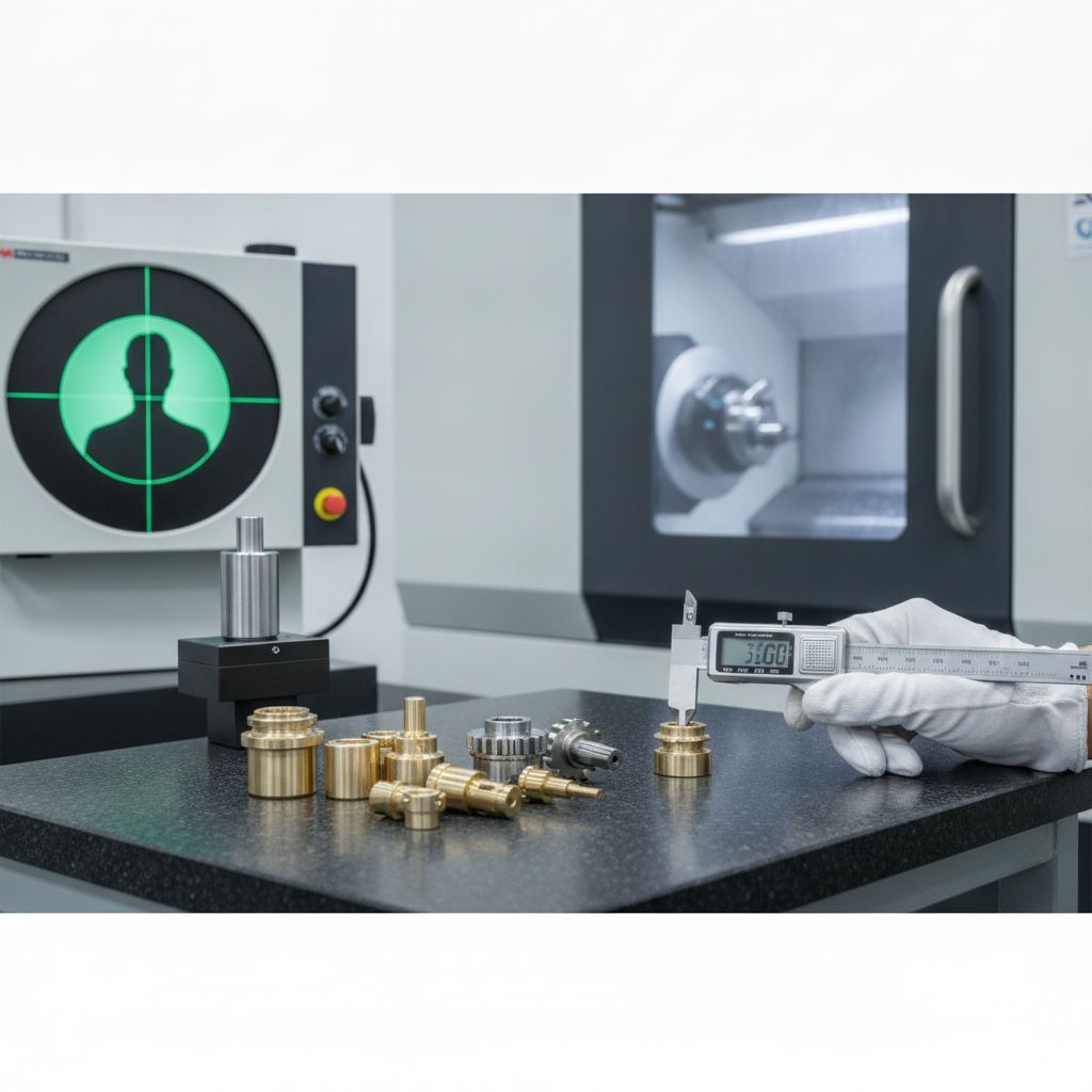
Basic dimensional inspection tracks nominal diameters, overall lengths, internal bores, groove depths, and thread pitches using calibrated digital calipers, micrometers, bore gauges, and dial indicators. Nevertheless, high-precision pins, shafts, cylinder cores, and bushings demand scrutiny beyond simple linear dimensions. Geometric Dimensioning and Tolerancing (GD&T) governs real-world mechanical relationships, including coaxiality, total radial runout, cylindricity, perpendicularity, and true position. For example, a minor runout deviation in a lock cylinder plug or an internal tumbler channel can cause mechanical friction, cylinder binding, or accelerated internal wear. To measure these complex geometric relationships accurately, technicians rely on profile projectors, optical measuring systems, and multi-axis Coordinate Measuring Machines (CMM).
Surface Finish Roughness and Burr Management
Spindle rotational speeds, linear feed rates, coolant lubrication, and tool nose geometry directly dictate the surface topography of a machined component. Surface roughness, conventionally quantified through Ra (arithmetical mean roughness) or Rz (mean peak-to-valley height) parameters, is a decisive factor for components exposed to dynamic friction, hydraulic pressure, or elastomeric sealing rings. Surface profilometers measure these micro-grooves to confirm that the workpiece adheres to specified micro-inch or micrometer thresholds. Simultaneously, micro-burrs forming at cross-hole intersections, thread entries, and parting-off faces must be identified under optical magnification. Reliable contract facilities subject such components to secondary deburring, edge breaking, or automated vibratory tumbling before final release.
Material Integrity and Hardness Verification
Geometric precision is ineffective if the underlying metallurgical substrate cannot withstand operational stresses. Contract turning requires validating raw material test reports against chemical and mechanical standards to ensure proper material grade, tensile strength, and machinability. When specialized structural properties are required, optical emission spectrometry confirms alloy composition. For components subjected to post-machining induction hardening, carburizing, or quenching, surface and core hardness must be tested via Rockwell or Vickers methods to ensure wear resistance without causing excessive brittleness. In industrial applications where mechanical toughness must precede machining, processes such as cold forging press stamping are implemented, requiring similar structural and hardness validation steps before secondary precision finishing takes place.
Defect Prevention Protocols in High-Volume CNC Production
Modern CNC automatic lathes can fabricate hundreds of intricate pins, shafts, or fittings in an hour. At this production cadence, identifying an error after thousands of units have been run creates unsustainable losses. Forward-thinking manufacturing partnerships focus on preventive control structures that intercept process shifts before parts exceed acceptable tolerance bands.
First Article Approval and CNC Tool Offsets
Whenever a lathe is set up, tooling is re-indexed, or a new machining program is initiated, the first produced sample undergoes exhaustive multi-point measurement. Technicians map every linear dimension, angular feature, chamfer, and thread profile against the engineering drawing, recording the data in a dedicated First Article Inspection (FAI) report. Mass processing begins only after this report is signed off. Throughout the shift, as cutting edges sustain microscopic wear or ambient temperatures warm the machine casting, operators enter micron-scale tool offsets into the CNC controller, pulling critical dimensions back to the nominal centerline of the tolerance band.
In-Process Sampling and Coordinate Measuring Machine (CMM) Audits
During live runs, operators execute statistical process control (SPC) by sampling parts at scheduled intervals. Technicians check these parts using calibrated bench gauges, thread rings, or optical comparators, logging the dimensions to identify directional drift. When processing intricate lock components, valve spools, or multi-featured turned parts, components are transferred to temperature-controlled quality rooms for CMM verification. These multi-sensor machines rapidly scan complex coordinates, generating inspection plots that reveal tool wear patterns and thermal drift long before parts reach their upper or lower specification limits.
Common Quality Pitfalls in Contract CNC Turning Operations
Discrepancies in contract machining typically originate from recurring technical and procedural gaps. Recognizing these vulnerabilities allows purchasing teams and engineers to clarify requirements before signing purchase orders:
- Ambiguous Engineering Drawings: Failing to clearly specify geometric tolerances, allowable burr limits, surface roughness values, or edge breaks leaves critical decisions to operator discretion, frequently resulting in parts that pass dimensional checks but fail during assembly.
- Unmonitored Cutting Tool Degradation: Extended machining without systematic tool life tracking causes progressive flank wear. This wear manifests as tapered shafts, poor surface finishes, thermal discoloration, and oversized thread pitch diameters.
- Inconsistent Raw Bar Stock Tolerances: Swiss-type CNC lathes rely on tight clearances between the guide bushing and the ground bar stock. If incoming raw material exhibits diameter fluctuations outside standard grades (such as h8 or h9), the stock can bind or chatter, leading to severe coaxiality errors.
- Deficient Cleaning and Protection: Residual neat cutting oils, micro-chips trapped in blind threaded holes, and inadequate compartmentalized packaging during transport often result in scratched critical diameters or corrosive spotting before the parts reach customer inventory.
Frequently Asked Questions Regarding CNC Part Inspection
How frequently should dimensions be measured during continuous CNC runs?
Inspection frequency is determined by component criticality, tolerance tightness, and machine capability. Standard operational practice calls for in-process sampling on a time-based cadence (such as hourly) or a batch-count basis (such as every 50 to 100 finished parts). A complete first article inspection must be performed at every shift change, after each cutting tool insert replacement, or following raw material bar loading.
Are Go/No-Go plug and ring gauges sufficient for precision turned parts?
Fixed-limit Go/No-Go gauges provide rapid, cost-effective verification on the production floor, making them useful for sorting acceptable components from rejects. However, they do not output numerical data or show where a dimension falls within its tolerance band. To detect tool wear and process drift early, variable metrology tools—such as digital micrometers, dial bore indicators, and optical vision systems—must supplement fixed limit gauges.
How should quality acceptance criteria be formally documented for suppliers?
Acceptance standards should be codified through a formal Quality Inspection Plan (QIP) integrated into the manufacturing contract. This document must list every controlled feature, specify the exact measurement instrument to be used, define sample sizing, and state the targeted Acceptable Quality Limit (AQL) alongside material test report requirements.
How do quality checks for cold-formed blanks differ from CNC turned components?
While machining focuses on chip clearance, tool marks, and sharp mechanical boundaries, metal part forming with cold forging technology prioritizes material flow lines, die cavity fill, internal stress relief, and grain direction. Cold forged blanks are frequently transferred to CNC automatic lathes for secondary finishing operations that establish final precision tolerances on critical mounting faces.
Establishing Repeatable Excellence in Contract Manufacturing Partnerships
Sustainable success in mechanical engineering relies on measurable, repeatable quality standards. Whether producing master-keyed cylinder components, high-security padlock bodies, or custom turned hardware, components must assemble smoothly without manual fitting or line interruptions. When selecting a contract machining vendor, businesses should evaluate more than just unit cost; equal consideration must be given to the vendor’s metrology infrastructure, gauge calibration routines, and traceability protocols.
A collaborative framework built on complete technical drawings, documented inspection plans, and certified test reports protects production schedules from unexpected downtime. To discuss precision machining, custom mechanical hardware, or tailored quality assurance requirements for your specialized components, contact us today to review your project specifications with our engineering team.
İlginizi Çekebilir