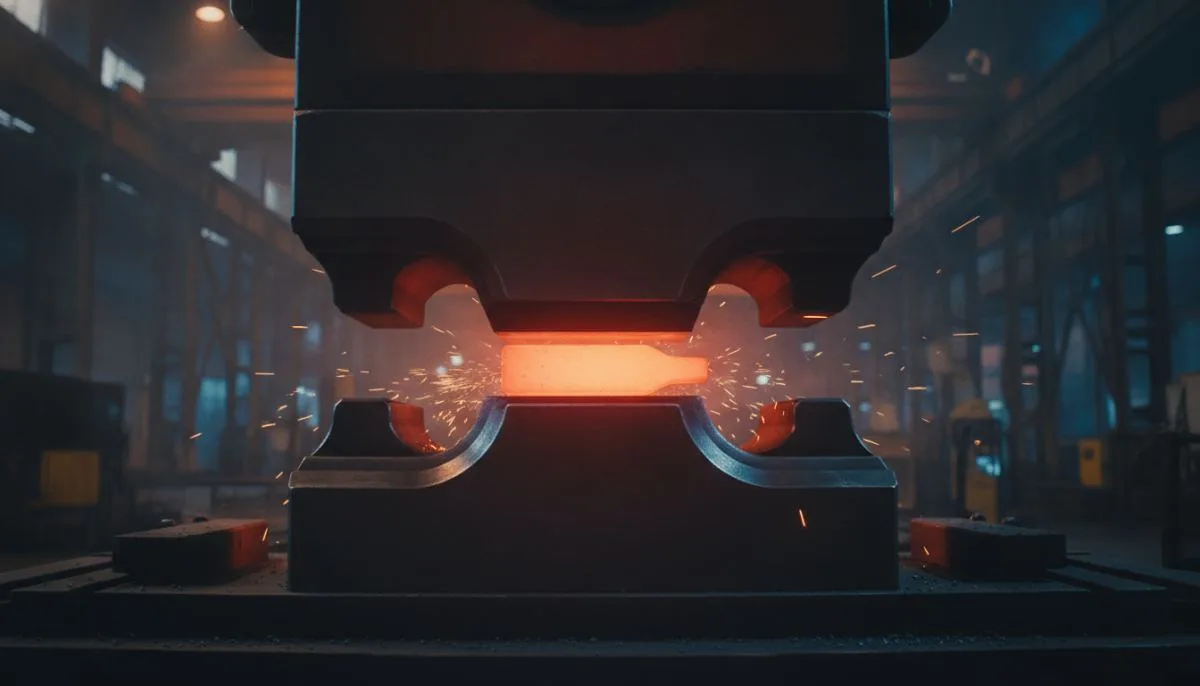
Flash Allowance & Die Design in Hot Forging Presses
Learn how flash allowance and flash gutter geometry impact hot forging die design. Explore calculation criteria and engineering steps to optimize tooling.
In modern industrial manufacturing, hot press forging remains indispensable for producing structural components that require exceptional mechanical strength, refined grain structure, and high fatigue resistance. Widely utilized in the production of heavy-duty hardware, automotive components, and lock bodies, the ultimate quality of hot-forged parts depends heavily on robust die design and the precise calculation of flash allowance. The complete filling of complex die cavities, the direction of metal flow, and the prevention of catastrophic stress concentrations on hydraulic or mechanical presses are directly governed by the engineering behind the flash land and gutter.
For manufacturers looking to minimize scrap rates, balance press tonnage requirements, and control subsequent trimming costs, flash allowance is far more than excess raw material. An improperly calculated flash geometry can lead to early tool failure, catastrophic die cracking, or defective parts with incomplete filling. Understanding the underlying metallurgical dynamics and structural behavior of heated billets during plastic deformation is therefore critical to establishing viable tooling geometries and dimensional tolerances.
What Is Flash Allowance in Hot Forging and Why Does It Matter?
In impression-die hot forging, flash allowance refers to the engineered excess volume of metal designed to escape the main cavity into a restricted opening. As heated stock is placed into the lower die and compressed by the upper die stroke, the material expands outward to fill the contours of the engraving. The instant the cavity approaches complete filling, excess plasticized metal is forced through a narrow restriction termed the flash bridge or flash land, exiting into a broader relief pocket known as the flash gutter.
The primary engineering function of this narrow bridge is to generate localized flow resistance. As the escaping metal enters the narrow land, friction and rapid surface cooling increase back-pressure significantly. This localized resistance forces the remaining heated core within the cavity into higher hydrostatic pressure, driving the plasticized metal into fine details, thin ribs, sharp radii, and intricate projections that would otherwise remain unfilled. Without this controlled resistance, the unconstrained material would simply spill outward along the path of least resistance, leaving the component defective.
Consequently, flash allowance establishes an essential equilibrium between cavity fill assurance and the structural life of the tooling. Designing too little flash restriction prevents adequate pressure build-up, causing cold shuts, underfilling, and rounded part contours. Conversely, an excessively restrictive or narrow flash land causes immense pressure spikes, straining press capacity and subjecting the die steel to severe tensile stresses that accelerate fatigue cracking. For select tight-tolerance components, precision Cold Forging Press Operations can eliminate or dramatically reduce flash; however, for complex structural components undergoing severe plastic deformation, optimized hot forging flash remains the standard method to guarantee structural density.
Flash Gutter Geometry and Calculation Criteria in Die Design
A functional flash channel in hot forging die design consists of two discrete zones: the flash land (bridge) and the flash gutter (pocket). The bridge directly borders the parting line of the cavity, acting as the primary flow restrictor. The gutter is the expanded trough adjacent to the bridge, designed to collect the extruded excess without exerting counter-pressure on the die blocks. Proper geometric sizing relies on several interdependent parameters:
- Bridge Thickness and Width: The thickness of the flash land dictates the cooling rate of the exiting metal, whereas the land width governs frictional resistance. Larger, heavier components typically require thicker lands to prevent premature chilling of the bridge, while the ratio of width to thickness directly controls internal hydrostatic pressure.
- Fillet and Transition Radii: Sharp transitions between the cavity profile and the flash land create acute stress raisers. Well-engineered blend radii ensure smooth material flow, preventing shear cracking along the parting line and preserving unbroken grain flow along the part perimeter.
- Gutter Reservoir Volume: The flash gutter must possess sufficient volumetric capacity to contain all anticipated surplus material without bottoming out. If the extruded flash fills the gutter and contacts the outer boundaries, uncalculated forces will act directly upon the press ram and bolster plate, risking tooling breakage.
- Thermal Shrinkage Allowances: Workpieces undergo substantial thermal contraction as they cool from typical forging temperatures down to ambient levels. Die cavities and flash transitions must incorporate precise scaling factors based on the specific thermal expansion coefficient of the forged alloy (such as carbon steels, brasses, or alloy steels).
When developing tooling layouts, engineers must continuously mitigate premature wear mechanisms. Reviewing documented patterns in Causes of Wear in Hot Forging Press Dies helps designers reinforce high-friction transition points and optimize bridge sizing to prevent thermal fatigue cracking.
Step-by-Step Engineering Process for Hot Forging Die Design
Developing dependable forging tooling requires a rigorous engineering sequence combining empirical manufacturing standards with finite element simulation. Every stage, from initial raw billet heating to subsequent trimming and piercing, must be addressed systematically.
The process begins with an in-depth analysis of the finished component blueprint. Machining allowances, draft angles, and tolerance bands are established. Adequate draft angles must be integrated along vertical cavity walls to ensure the forged part releases freely without sticking or deforming upon die opening. Concurrently, the optimal parting line is determined. Selecting a balanced parting line minimizes asymmetric side-thrusts on the press guides, simplifies die machining, and balances flash formation evenly across mating die halves.
The second stage involves calculating volumetric requirements and raw billet dimensions. The total metal volume equals the net volume of the machined component, plus machining allowances, scale losses caused by furnace oxidation, and the calculated flash volume. Underestimating this sum risks non-fill defects, while overestimating it creates excess material waste and forces higher trimming tonnages. In high-precision hardware manufacturing, where tolerances approach the micron-level repeatability seen in Cold Forging Methods in Lock Pin Manufacturing, flash volume margins must be constrained within tight thresholds.
In the third stage, deformation sequencing is established. Complex geometries cannot be transformed from a simple cylindrical or square billet into a finished shape in a single stroke. Preforming stages—such as edging, fullering, bending, or blocker cavities—are introduced to redistribute the metal volume according to the final mass distribution. Finally, the finishing cavity, complete with flash land and gutter geometries, is modeled in CAD software and validated through finite element metal-forming simulation to observe material flow velocities, temperature gradients, and press load profiles.
Following digital validation, tool paths are generated for CNC machining. Hot-work tool steels (such as AISI H13, 1.2344, or 1.2714) are typically machined, heat-treated through hardening and tempering to achieve balanced toughness and wear resistance, and finished with specialized stress-relieving procedures.
Common Pitfalls in Flash Channel Design and Tooling Fabrication
Tooling downtime, dimensional variations, and frequent maintenance in forge shops can frequently be traced back to overlooked design nuances. One of the most prevalent issues is an unbalanced parting line. When a die parting plane is excessively stepped or tilted without counter-locking features, extreme lateral forces push against the press ram, creating horizontal die mismatch, premature guide rail wear, and irregular flash thickness around the part perimeter.
Another frequent error is specifying an overly restrictive flash land to overcome poor preform volume distribution. While forcing a tighter land will raise cavity pressure to help fill hard-to-reach pockets, it creates localized thermal stress and overpressurizes the tooling. This quickly leads to thermal fatigue, heat checking, and chipping along the cavity margins. Conversely, an excessively open flash land permits hot metal to escape into the gutter prematurely, causing incomplete filling in adjacent sections.
Additionally, inadequate venting in deep cavity recesses leads to trapped gases. As lubricants vaporize under intense heat, combustible gases can become compressed within blind pockets if venting channels are omitted. The resulting back-pressure prevents the advancing metal front from reaching corners, causing rounded features or surface pitting.
Comparing Hot and Cold Forming Die Philosophies
Metal forming methodologies utilize divergent design approaches depending on working temperatures. Hot forging heats billets significantly above their recrystallization temperature, lowering yield strength and increasing ductility. This makes flash gutters indispensable for managing volume variations and regulating pressure. Conversely, adopting Cold Forging Technology for Metal Parts involves shaping materials at ambient temperatures. Cold processes typically utilize completely closed dies or minimal-flash approaches, relying on precise billet shearing rather than open flash gutters.
In hot forging, the flash ring also serves as a protective buffer, absorbing minor billet volume variations and shielding the main cavity from excessive pressure concentrations. Both methods ultimately strive to align grain flow lines with the functional stress paths of the component, eliminating internal porosity and maximizing structural dependability for demanding applications.
Frequently Asked Questions
How is the flash bridge thickness determined during design?
Flash land thickness is typically calculated using empirical formulas that factor in the projected area of the forging, overall part weight, and material flow stress at forging temperature. Designers utilize established empirical coefficients, subsequently refining the dimensions using metal-forming simulation software.
What happens to the forged part if the flash land wears down?
As the flash land wears, the gap widens. This reduces the frictional resistance against the escaping material, leading to a drop in internal die cavity pressure. Consequently, the metal may fail to fill intricate ribs or corner radii, and the resulting part thickness along the parting line may fall outside required tolerances.
Is completely flashless hot forging possible in production?
Flashless hot forging is technically feasible utilizing closed-die tooling without gutters. However, it demands exceptionally tight billet volume tolerances, precise volumetric shearing, strict press ram repeatability, and robust multi-action tooling mechanisms to prevent catastrophic press overloading from slight volume variations.
Which tool steel grades are preferred for high-stress flash lands?
Because the flash bridge undergoes extreme sliding friction and rapid thermal cycling, hot-work tool steels possessing high hot-hardness and resistance to thermal shock—such as 1.2344 (AISI H13) or 1.2714—are standard choices. Secondary surface enhancements, such as nitriding, are frequently applied to further prolong tool life.
Properly engineered tooling and optimized forging parameters are critical to sustaining consistent quality throughout long production runs. Whether your facility requires custom structural hardware, specialized industrial components, or advanced engineering support, please contact us to discuss your manufacturing requirements with our technical team.
You May Also Like Kopyala